After lots of great feedback from the folks at the
Canadian Guitar forum,
diyAudio, and
TDPI I have:
- a new chassis size and material consideration
- an expanded list of modifications
- new schematic
- new layout
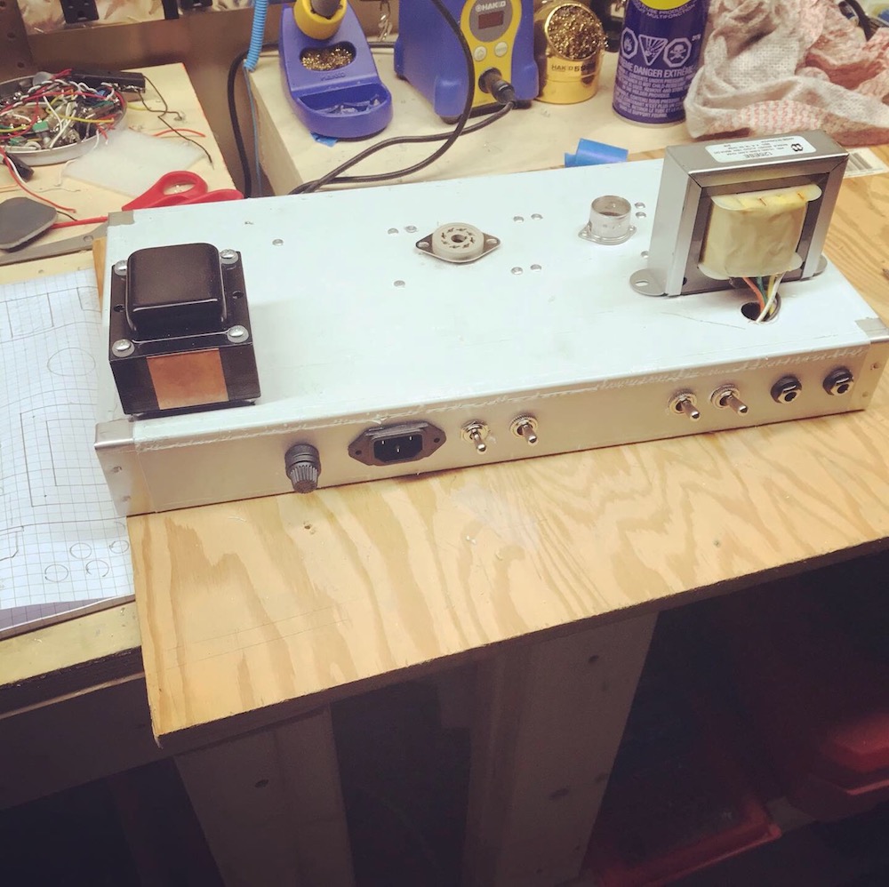
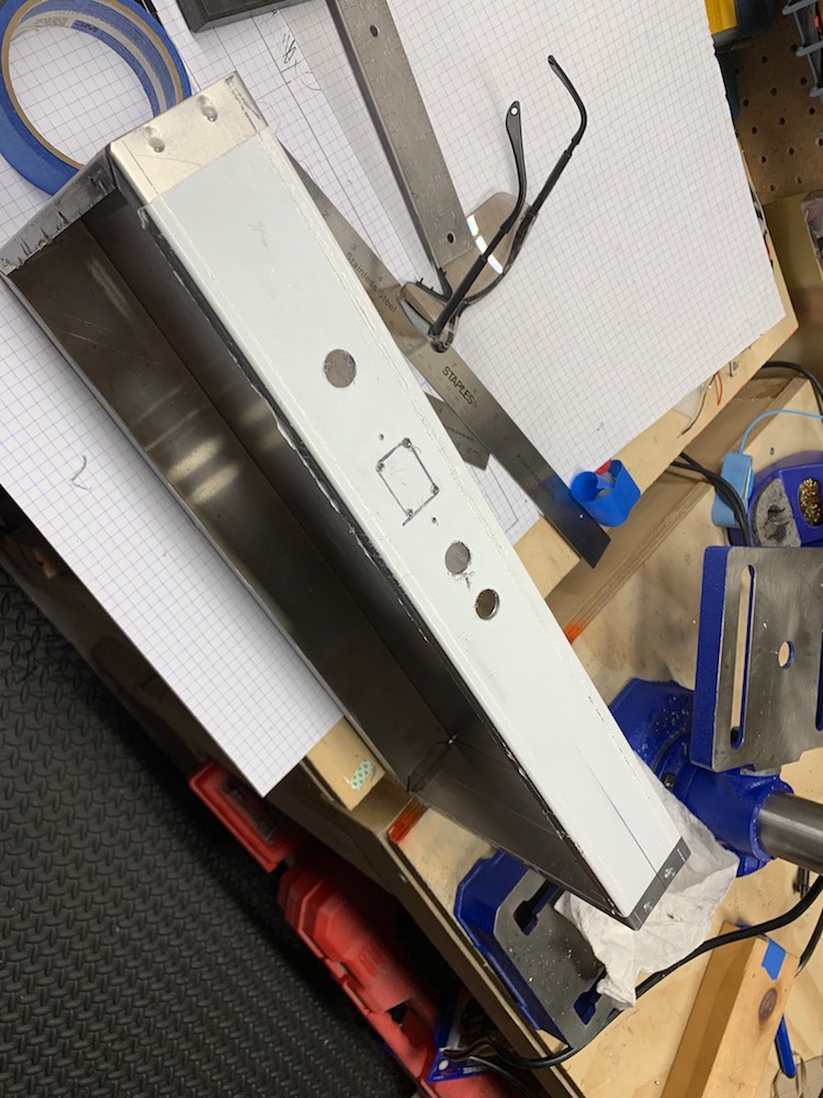
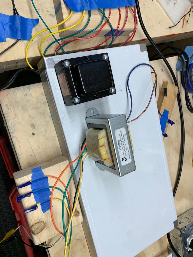
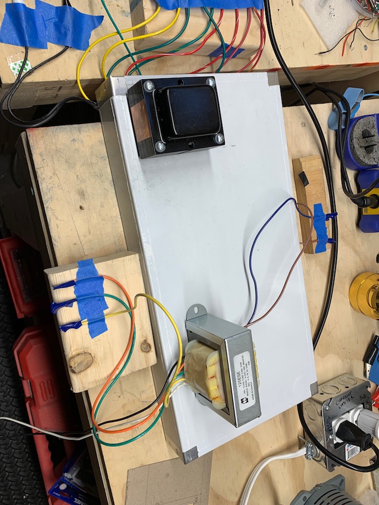
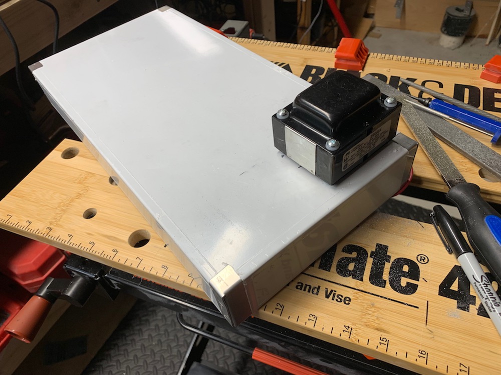
Chassis
Size: Bigger!
Many folks expressed concerns with my proposed 12" x 8" x 2"
chassis.
They are right. As much as I love the look of the
Greer Mini Chief or
Benson Vinny - I should go bigger.
This is my first build -- it's easier to build when you have more room.
This is kind of an experimental, hot-rod, tinkerer build -- it's not meant to look
pretty. It's meant to learn from and use as platform for experiments.
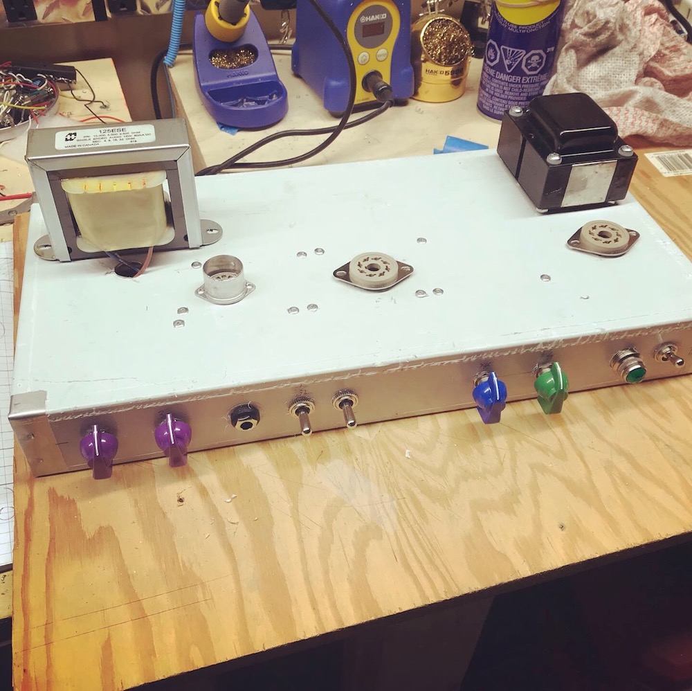
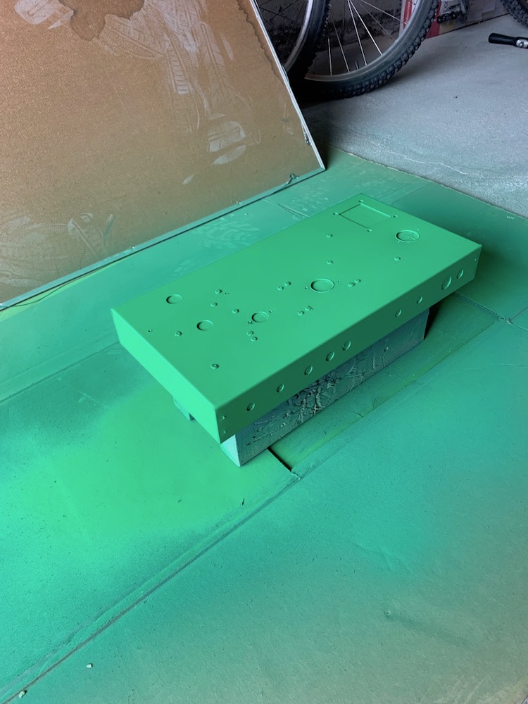
So ... I will bump up a size to 16" x 8" x 2"
chassis.
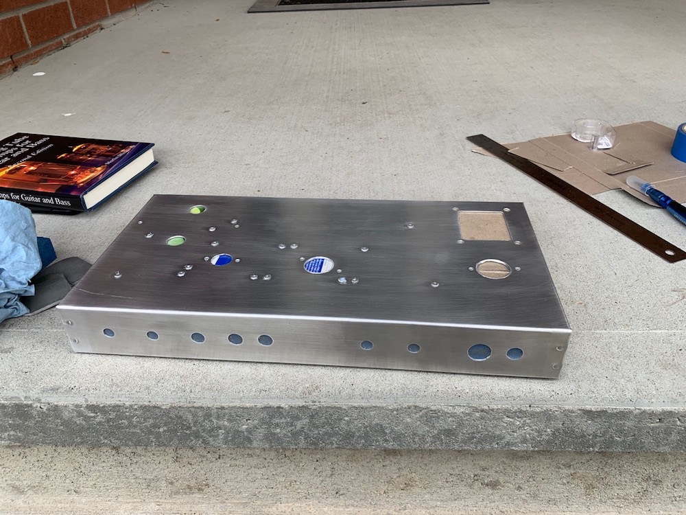
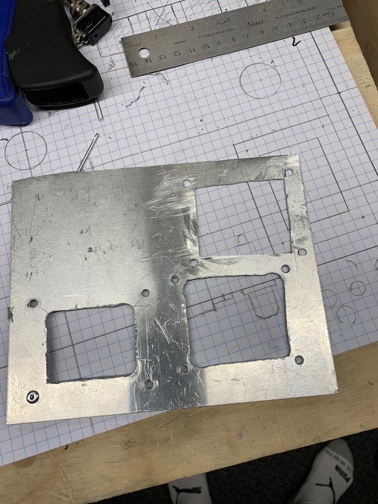
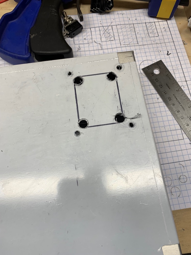
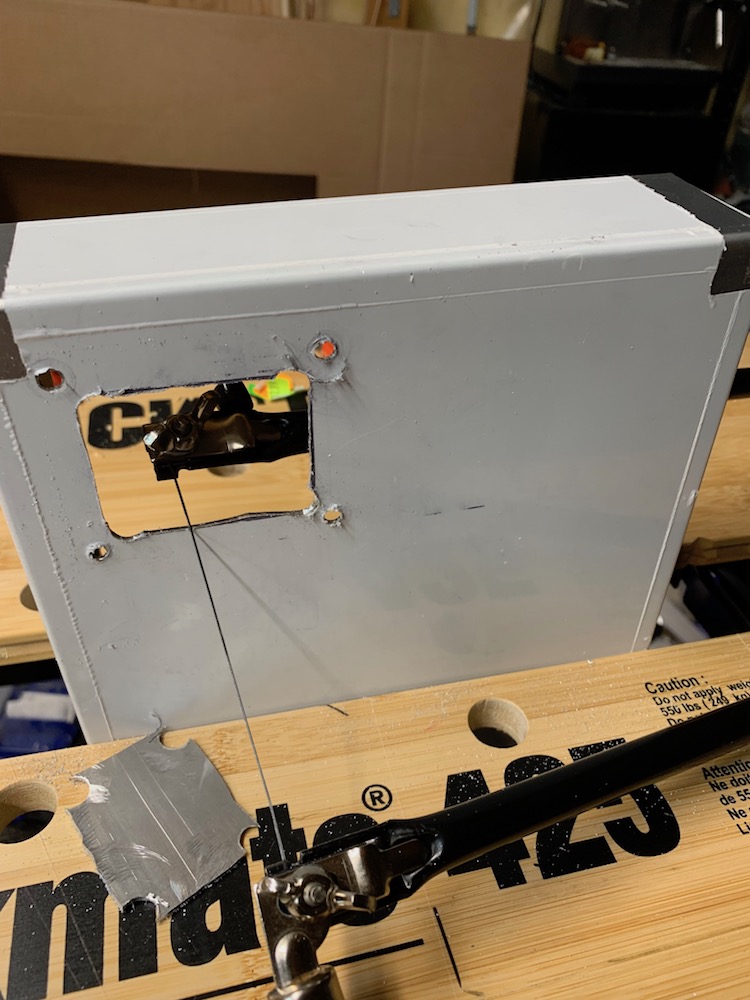
Material: Aluminum?
From the
link, you'll see the chassis is
aluminum.
Aluminum has many advantages for the chassis. It's easier to work, it's non-magnetic, etc.
However, some good folks went a bit further and and checked the manufacturer's
specs. The chassis is made out of 1.3 mm or 0.051 inches aluminum. This
may be too thin considering the transformers.
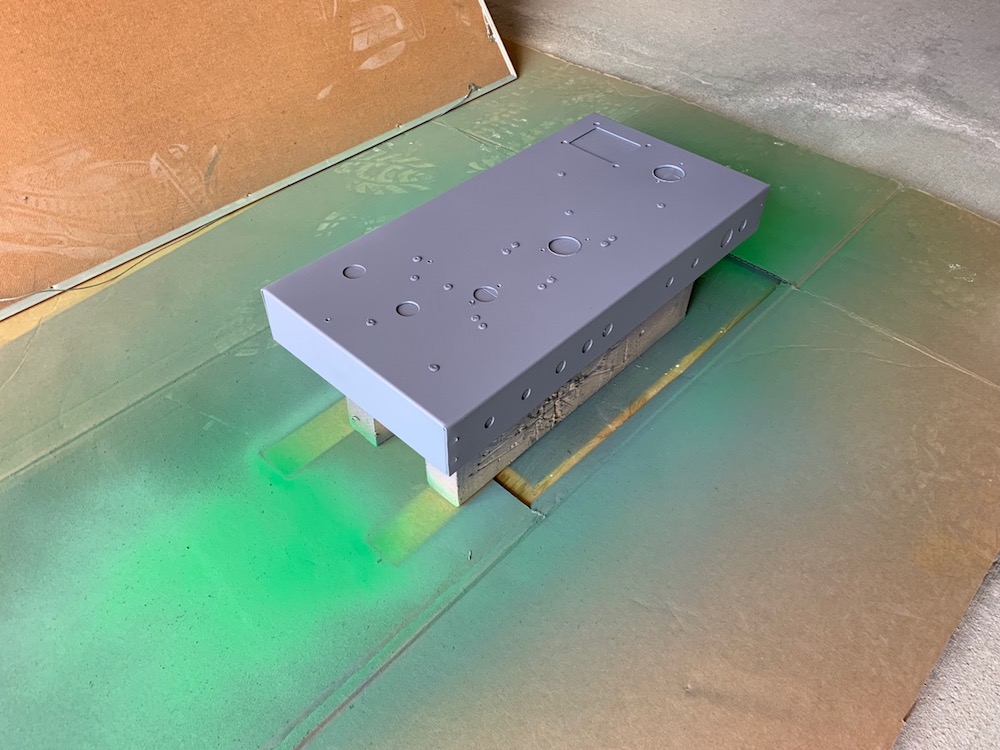
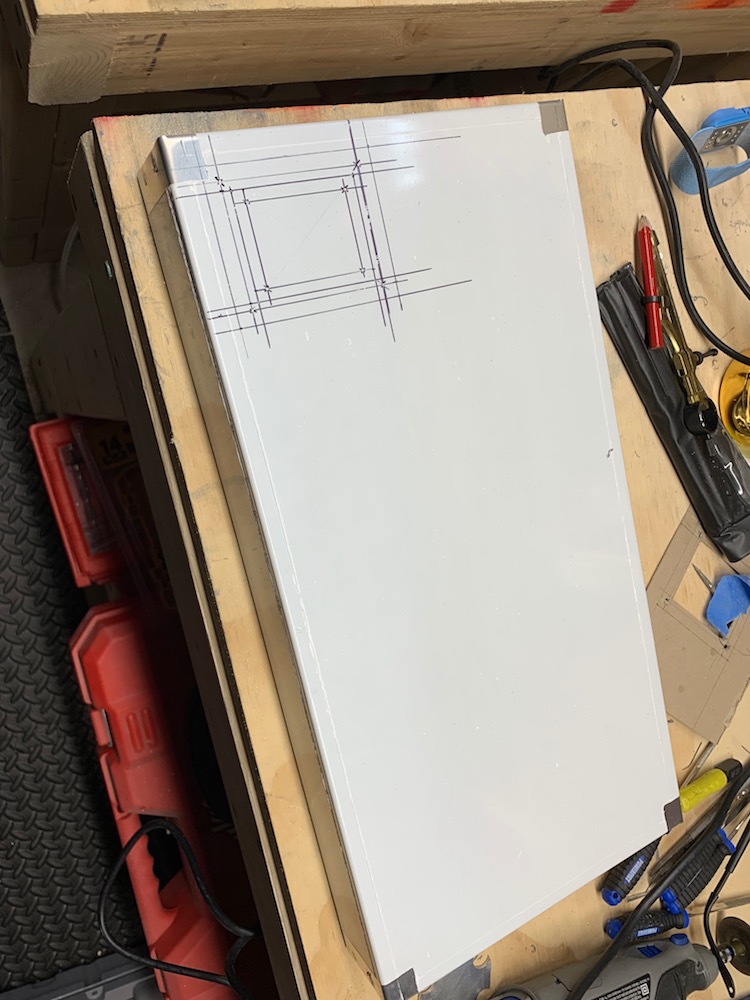
My plan is to order the chassis and see.
If it is too flex-y I can stiffen it with some aluminum channels -- as long as I keep that in mind when laying out the amp ;-)
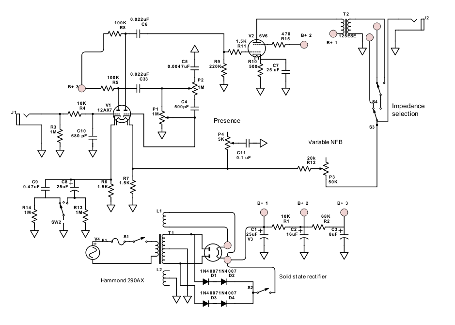
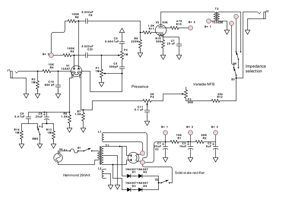
Modifications
Mod-1. Added a 470Ω
screen resistor to V2 (see forum
discussion), .
Mod-2. Added some SPDT switches to pick 3 of the 4 output transformer impedances.
Mod-3. Change R4, the 68KΩ
grid stopper on V1. I used the Merlin suggested 10KΩ + 680pF capacitor.
new Mod-4. Variable negative feedback
new Mod-5. Presence control.
This was suggested by
@mhammer and by watching
Uncle Doug: NFB and Presence.
I combined the two. If I understand correctly, the first pot controls the amount
negative feedback, and the second will decide how much of the frequency gets rolled off.
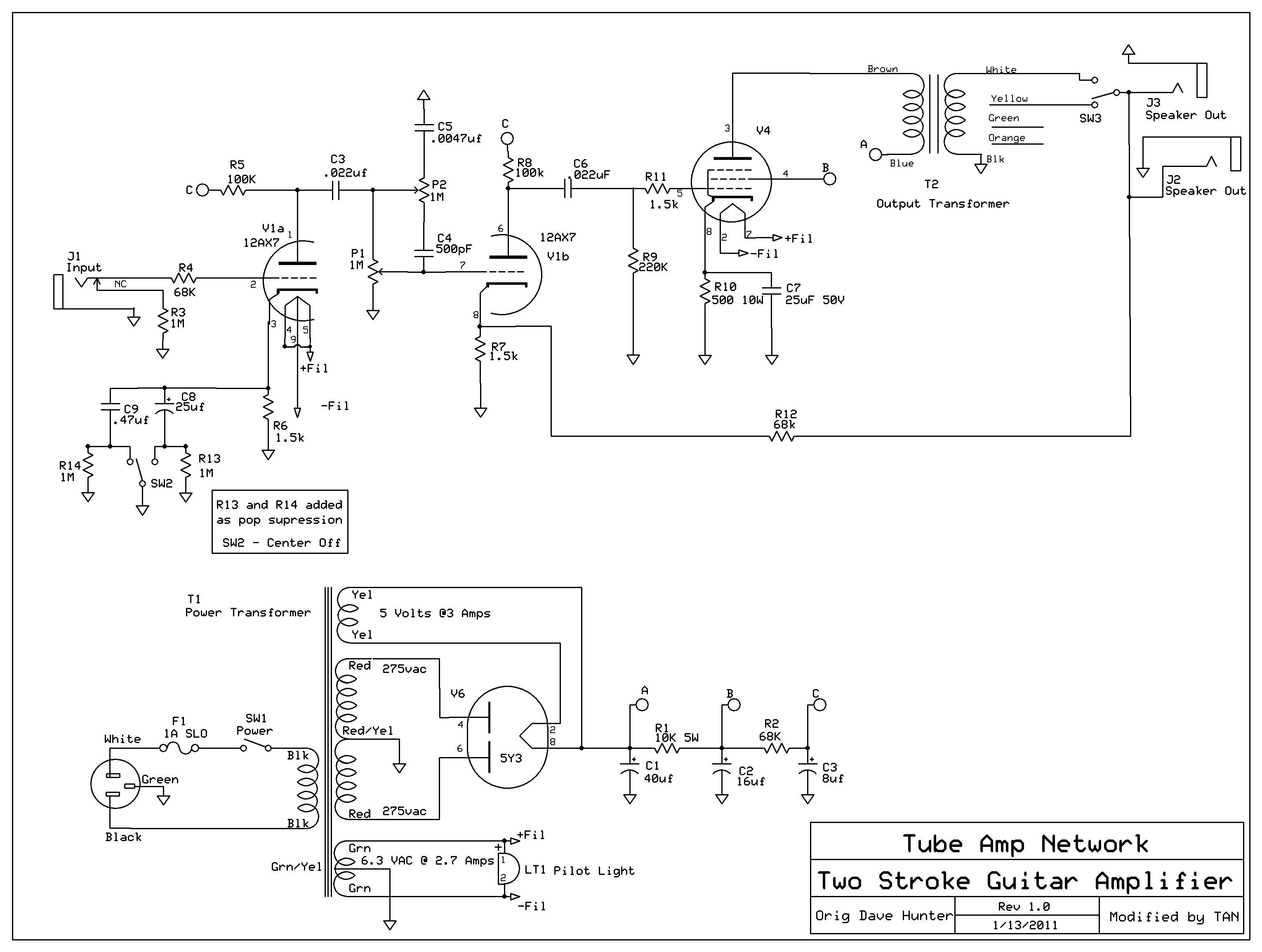
new Mod-6. Switchable Solid State Rectifier.
I saw this in a
post and
post on the
Tube Amp Network.
pending Mod-7. @mhammer also suggested a neat mod where instead of voicing
switch you replace it with a W-Taper hooked up to the 2 bypass caps so you could vary the amount of bypass.
I don't have the pot now, but there should be plenty of room to replace the switch in the future.
Speaking of W-taper pots, I found an interesting
page in Spanish which sounds like it allows you to simulate the pot with regular pots and resistors.
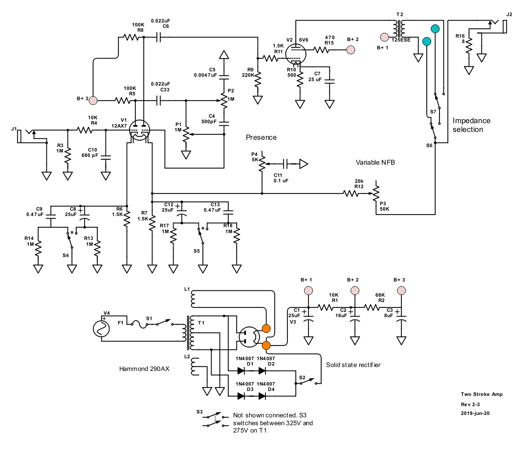
Schematic
Here's the revised schematic using
SchemeIt
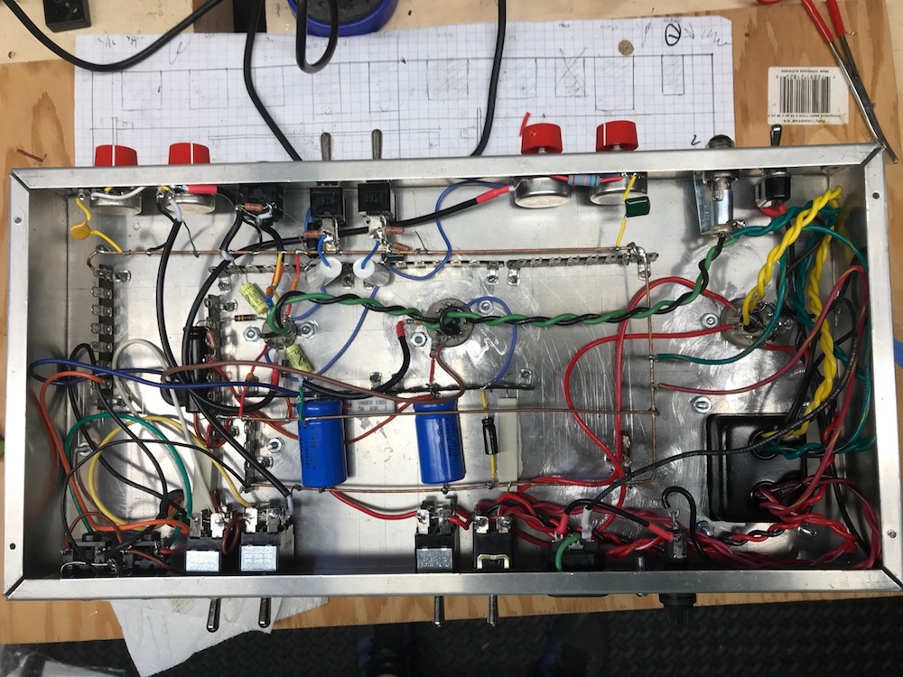
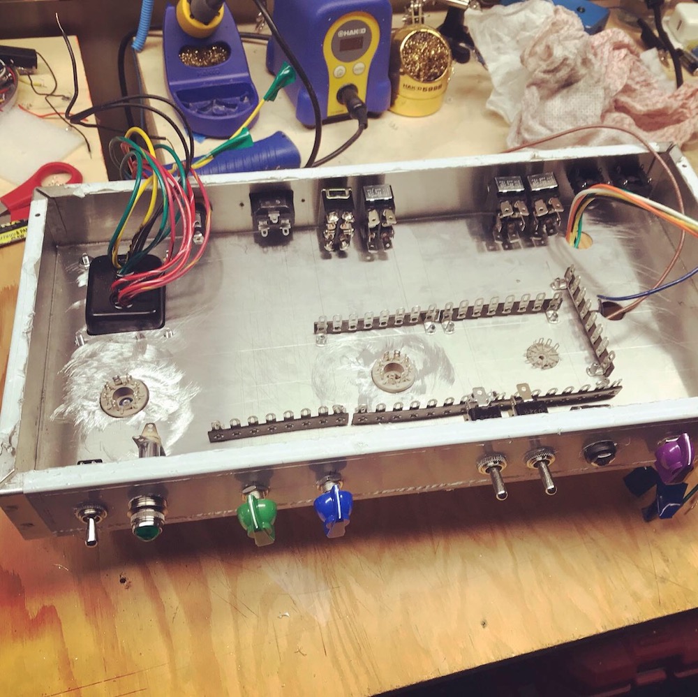
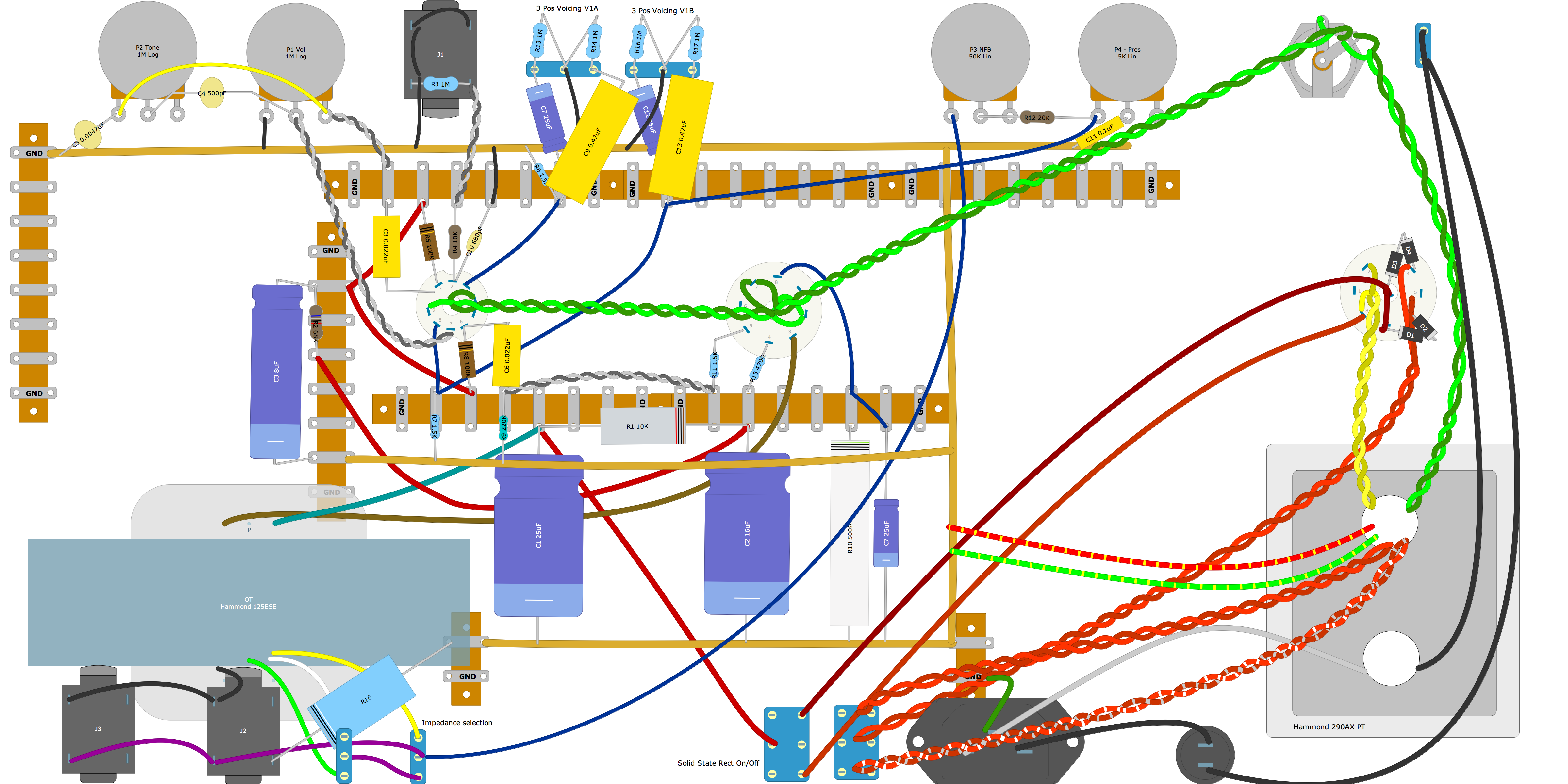
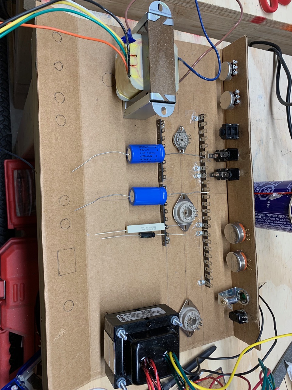
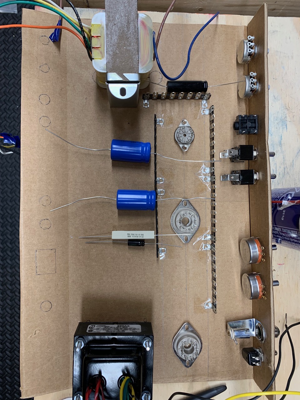
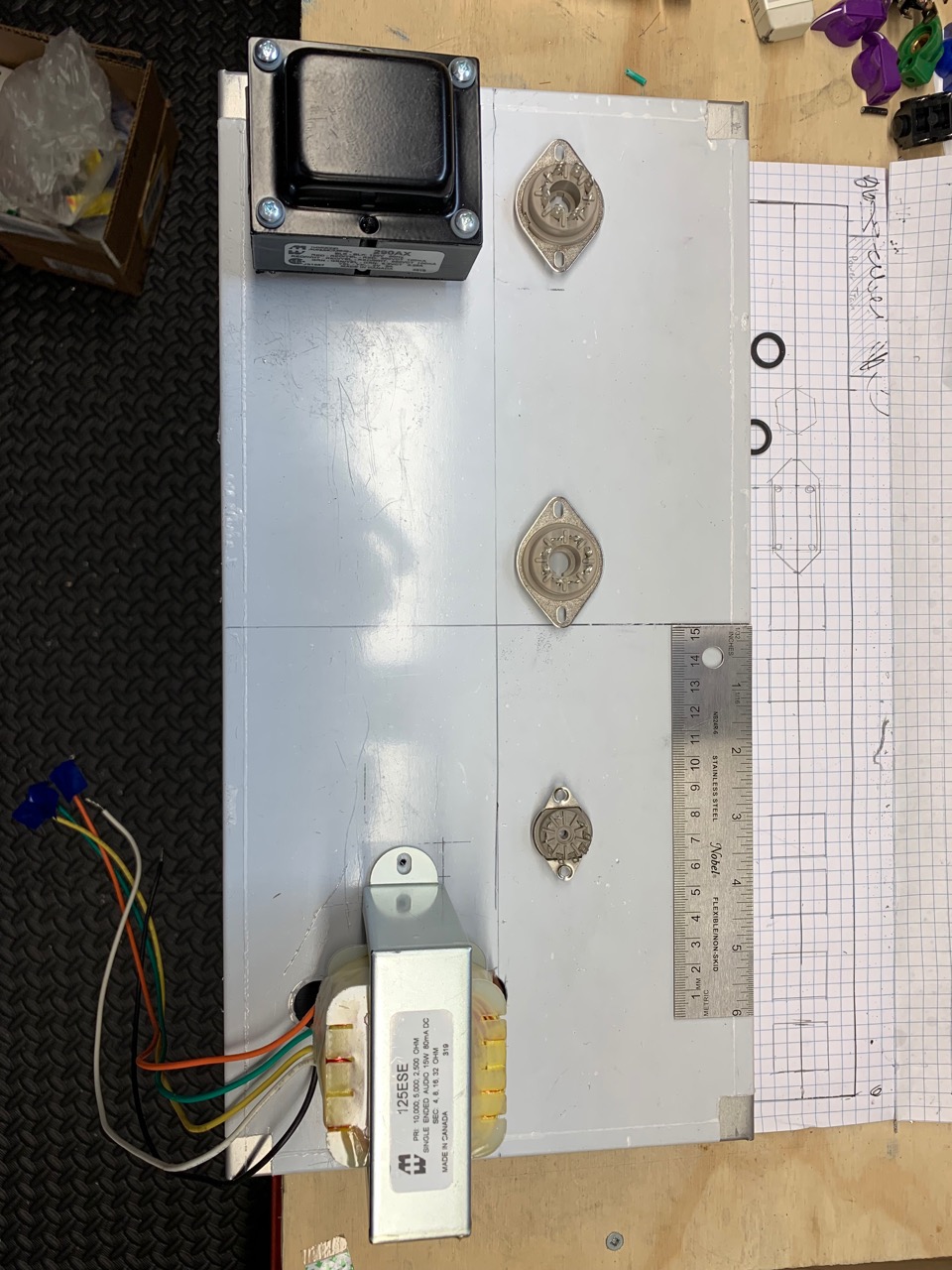
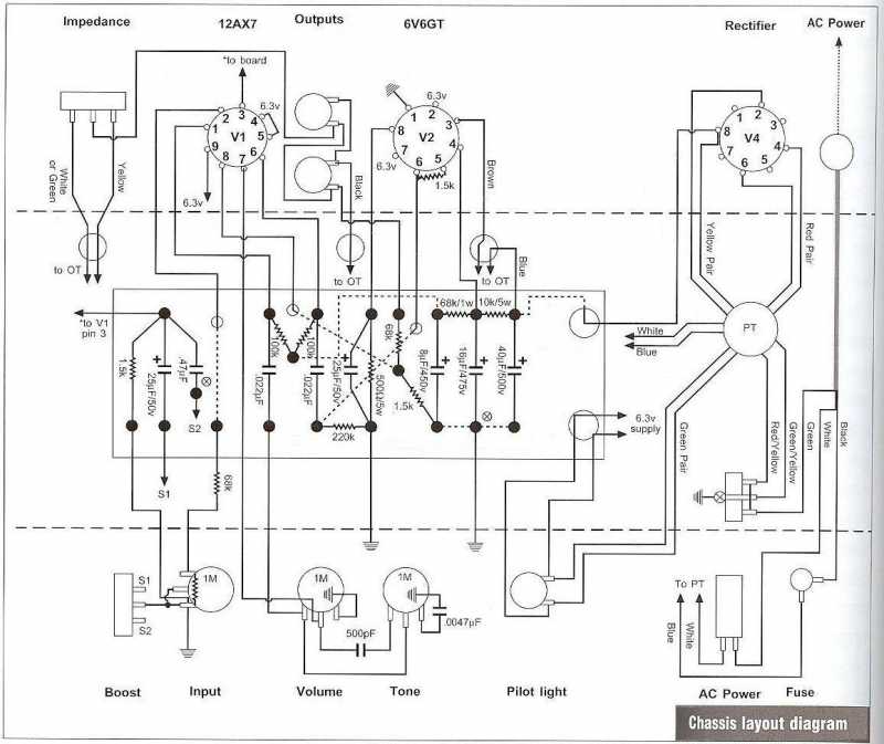
Layout
R.G. Keen's
article had some great point-point tips.
Here's the next layout.
Note: I changed the orientation -- you are now looking at the amp from the bottom as opposed to looking
through the top.
Why?
- This way seems to match the tube pin number order in the software
- It is what it will look like when I am building the amp


