Mods Status
Mod-1. Added a 470Ω screen resistor to V2 (see forum discussion), .
Mod-2. Added some SPDT switches to pick 3 of the 4 output transformer impedances.
Mod-3. Change R4, the 68KΩ grid stopper on V1. I used the Merlin suggested 10KΩ + 680pF capacitor.
Mod-4. Variable negative feedback
Mod-5. Presence control.
This was suggested by @mhammer and by watching Uncle Doug: NFB and Presence.
I combined the two. If I understand correctly, the first pot controls the amount negative feedback, and the second will decide how much of the frequency gets rolled off.
Mod-6. Switchable Solid State Rectifier.
I saw this in a post and post on the Tube Amp Network.
pending Mod-7. @mhammer also suggested a neat mod where instead of voicing switch you replace it with a W-Taper hooked up to the 2 bypass caps so you could vary the amount of bypass.
I don't have the pot now, but there should be plenty of room to replace the switch in the future.
new Mod-8 Safety load on OT
With all that switching on the output of the transformer, you really need to put a 1000 ohm 3 watt resistor right on the output of the transformer. That way if a contact in a switch oxidizes in future & doesn't make contact, the transformer doesn't short a turn from excessive voltage.
(from indianajo)
new Mod-9 Second cathode bypass
I would add a 25uF switchable cathode bypass to V1B for a 5E3 position.
(from RobRob)
new Mod-10 Hi/Low voltage switch
The Hammond 290AX has two secondary high voltage options: 325V and 275V.
In Episode 13 of Truth about Vintage Amps podcast, Skip mentions that the 275V option is useful for making an amp sound like an older Champ.
Back Panel Switch note: All of the back panel switches should only be changed while the amp is off
- Voltage Hi/Lo
- Rectifier Tube/Solid Stae
- Impedance selection
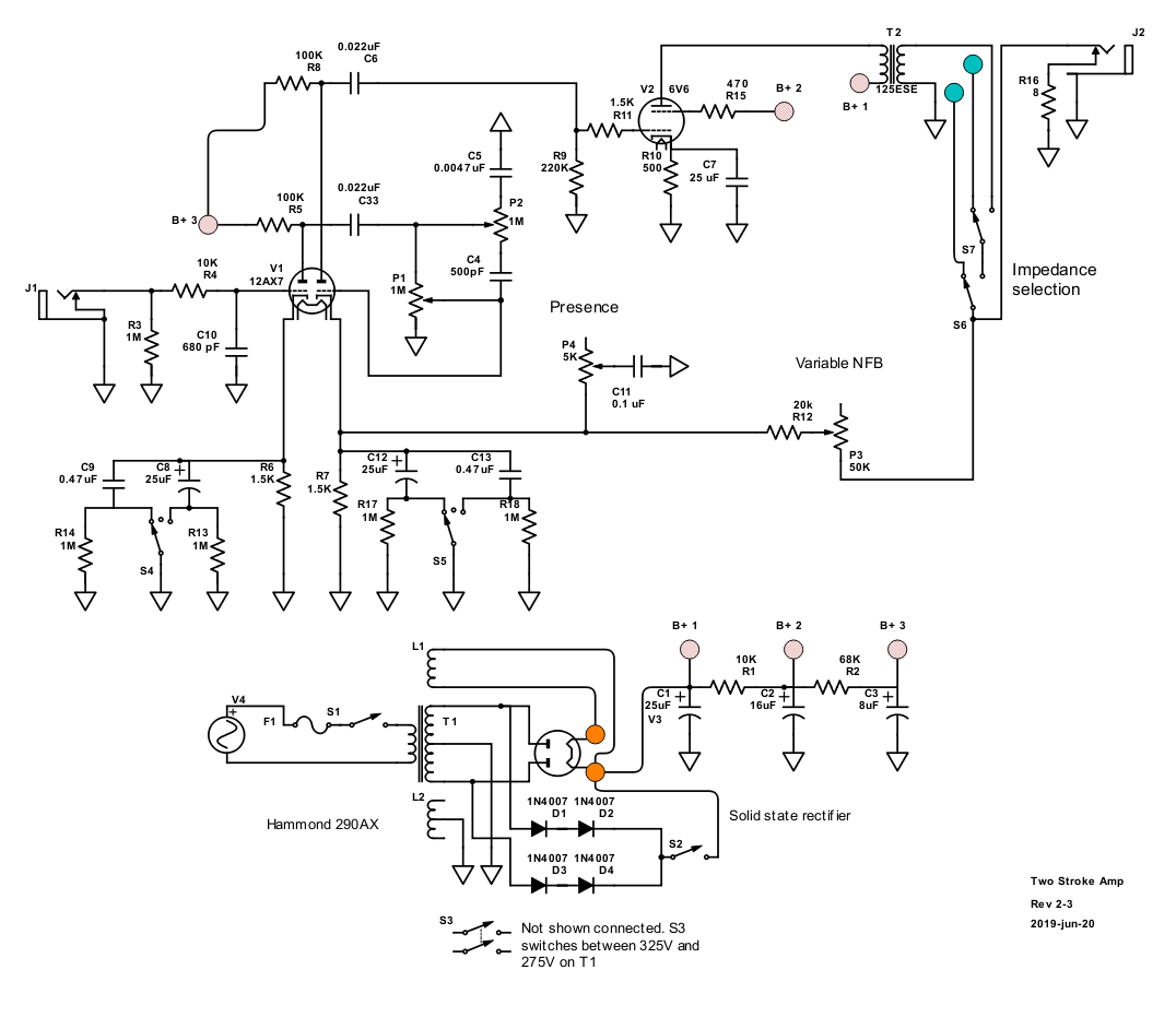
Revised Schematic - Rev 2-3
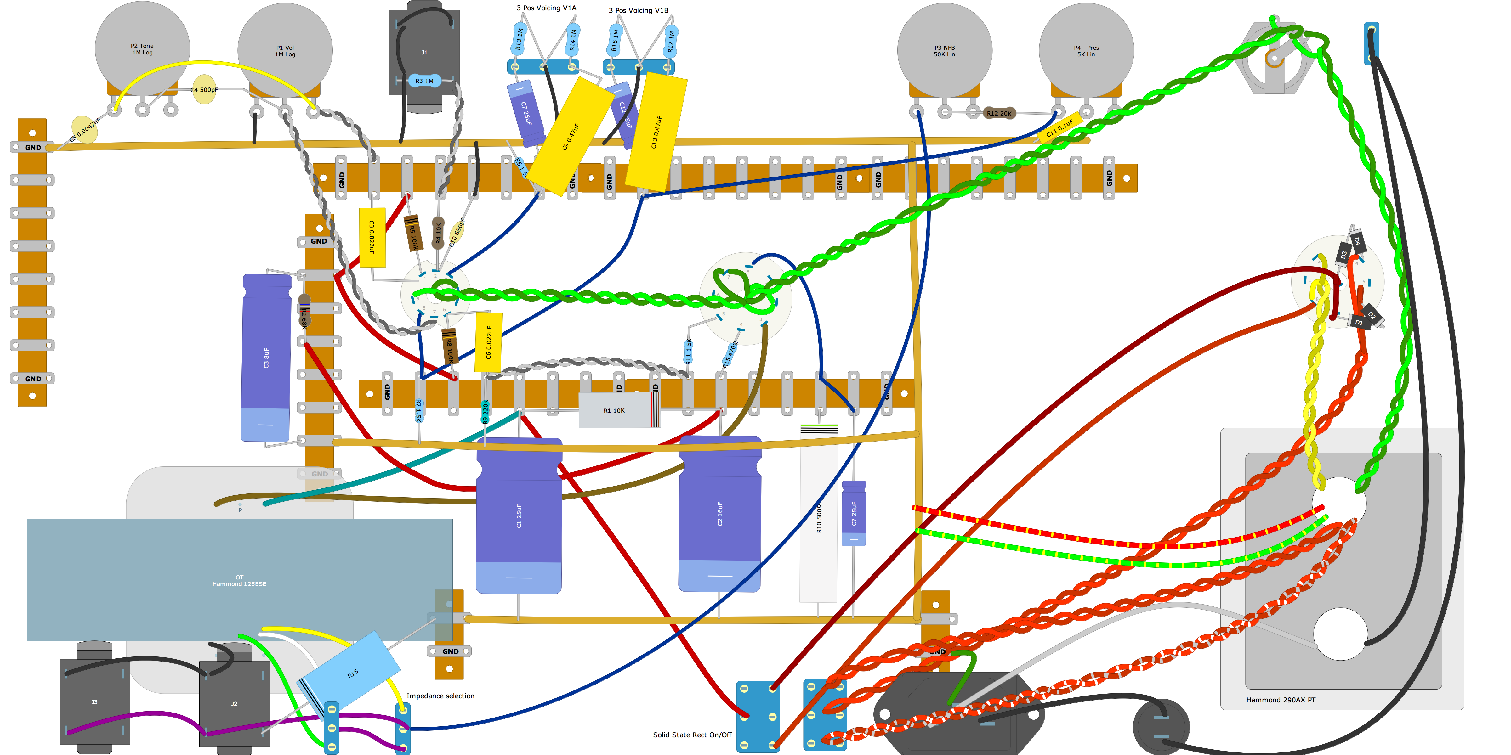
Revised DIY Layout
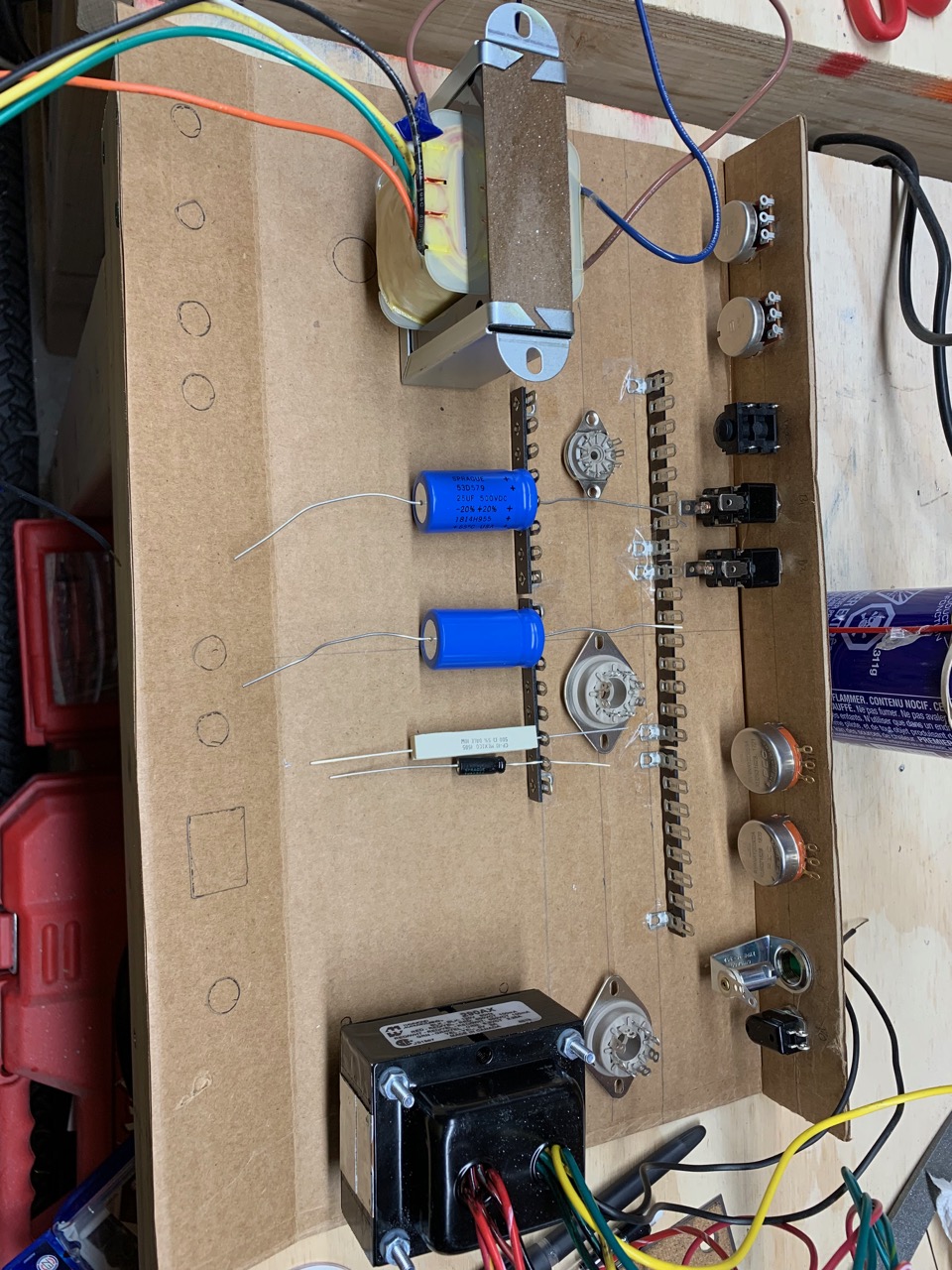
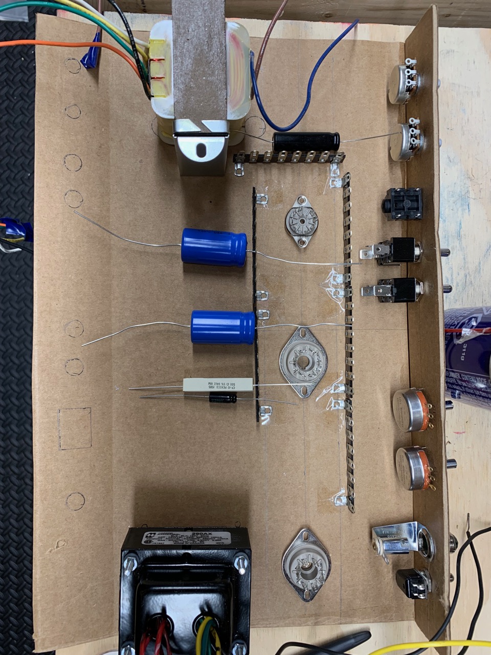
Cardboard Mock Ups
Before drilling wth front panel, tube sockets and terminal holes I started mocking up the amp in cardboard.
Based on previous picture RobRob mentioned that although the output transformer was isolated from the power transformer, it was now close to V1. Based on the mock ups, I think it will be ok because:
- its off to the side of the OT (although Morgan Jones does say that there is more leakage at the corners of the core)
- I plan on using a shielded V1
- I plan on using shield cable for the signal
Slight angle, looking from back to front
Top down
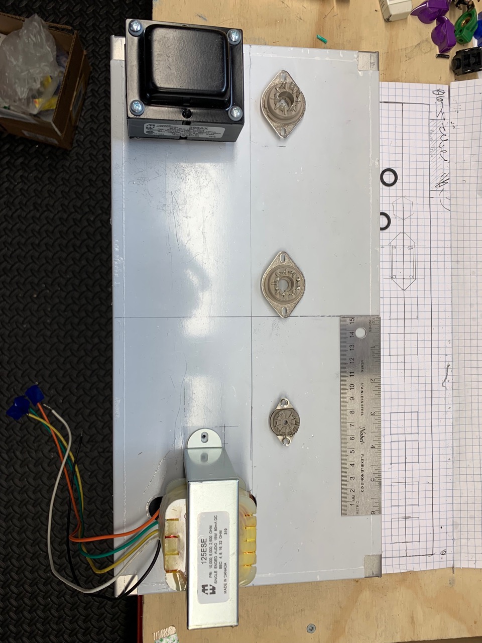
Tubes + Transformers
Laying out the tube sockets on top with the transformers (and using the approximate measurements from the mock up) I see something like this:
Some thoughts:
- I could go with the current layout and see what happens.
- I might be able to move the tubes about ½ inch closer to the front of the chassis (right now the tube centre line is 3 inches from the front).
- I could plug the existing holes for the OT and move it towards the PT. I could also move V1 as close as possible to right side of the chassis. I don't know if this will make much difference unless I move the OT very close to the PT. As JunoMike and OldJoat suggested I could look at making shield.